
Controlled-source Electromagnetics (CSEM) and Audio-frequency Magnetotellurics (CSAMT)

Overview
Controlled-source EM (CSEM) is a low-impact, ground geophysical survey method used extensively in minerals, geothermal, and groundwater exploration—and in some hydrocarbon applications—since 1978 when Zonge introduced a digital CSEM data-collection system to the industry, initially for Exxon Minerals.
The CSEM/CSAMT geophysics method involves transmitting a controlled electric signal at a suite of frequencies into the ground from one location (transmitter site) and measuring the received electric and magnetic fields in the area of interest (receiver site).
The ratio of orthogonal, horizontal electric and magnetic field magnitudes (e.g. Ex and Hy) are used to calculate the resistivity structure of the earth. Calculated resistivity values from CSEM / CSAMT data relate to geology.
Applications
Factors determining resistivity include rock or sediment porosity, pore fluids, and the presence of certain mineral assemblages. This makes CSEM / CSAMT data desirable in providing critical information about geologic structure, lithology, water-table trends, fluid salinity and contaminant locations for mineral, hydrology, and petroleum investigations.
What’s CSAMT?
Controlled-source Audio-frequency Magnetotellurics (CSAMT) is a type of CSEM surveying in which the transmitter is placed in the far field from the receiver. Early in the development of the method this was done to simplify modeling the data using mathematics and software originally written for modeling natural-source (rather than controlled-source) MT data.
This is no longer necessary with modern software. Thus the method is referred to as “CSAMT” in early research, while today “CSEM” and “CSAMT” are essentially interchangeable terms.
Depth of investigation and resolution
CSEM / CSAMT is useful for mapping the 20 to 1,000 meter depth range. Vertical resolution is 5 to 20% of the depth.
Depth of investigation depends on the transmitted frequency and resistivity of the subsurface. In general, the lower the frequency and the higher the ground resistivity, the greater the depth of the data.more
Lateral resolution is determined by station spacing. Station spacing is typically between 10 and 200 meters. The received signal strength is proportional to the size of the station spacing. For example, if the station size is cut in half, the signal strength is cut in half. This is important to remember when designing a survey because the limiting factor on depth of exploration is usually the signal strength.
Logistics
A Zonge CSEM /CSAMT field crew usually includes four or fewer people with one pick-up truck at the transmitter site and one at the receiver site. Depending upon the depth of exploration and geologic conditions, the two sites are usually located between three and six miles (five to ten kilometers) apart.more
At the receiver site, equipment can be carried by backpack. No off-road driving is necessary. Using a specialized, multi-channel receiver, the electric field and one or more magnetic field measurements are acquired simultaneously on several stations. A remote, grounded dipole is used for electromagnetic signals: the two, grounded, current electrodes are spaced approximately 5000 feet (1500 meters) apart.
Placement of the transmitter and the connecting wires from the transmitter to each current electrode is a function of access. Wires and transmitter can be located anywhere between these two electrodes or at reasonable distances offline wherever access is available. For high-power use, the transmitter and generator are truck mounted.
A portable Zonge receiver amplifies, filters, processes, and records the received signals at individual stations. The transmitted signal is detected with short grounded dipoles (electrode pairs) and magnetic-field sensors. The receiver dipoles are surface wires, grounded using small, porous ceramic “pots” buried slightly into the soil. Usually one to seven stations of data can be collected in one setup. After acquiring data at one field setup, the crew moves the receiver, the pots, and the wires to the next set of stations.
Man-made objects such as radio transmitters, metal fences, and power lines can affect resistivity measurements. Good survey design will minimize this.
Deliverables
Modeled data can be presented in several forms: cross sections, plan views, fence or 3D diagrams. When stations are collected along several lines in the same area, data can be displayed in plan-view plots at a constant elevation (depth). Plan views help highlight trends between lines. Fence diagrams show 2D cross sections of the resistivity results in a spatially-relevant 3D context.
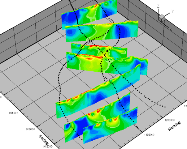
more
2D modeling corrects the measured data for terrain effects, uses information from adjacent stations, and does not assume that the subsurface variations in resistivity only occur vertically. Thus 2D modeling provides a better picture of the complexity of the geology at depth. 1D models preserve more near-surface detail and better reveal lateral changes such as thin, high-angle features.